 lockupADAMS报错资料.docx
- 文档编号:27092897
- 上传时间:2023-06-27
- 格式:DOCX
- 页数:17
- 大小:1.43MB
lockupADAMS报错资料.docx
《lockupADAMS报错资料.docx》由会员分享,可在线阅读,更多相关《lockupADAMS报错资料.docx(17页珍藏版)》请在冰豆网上搜索。
lockupADAMS报错资料
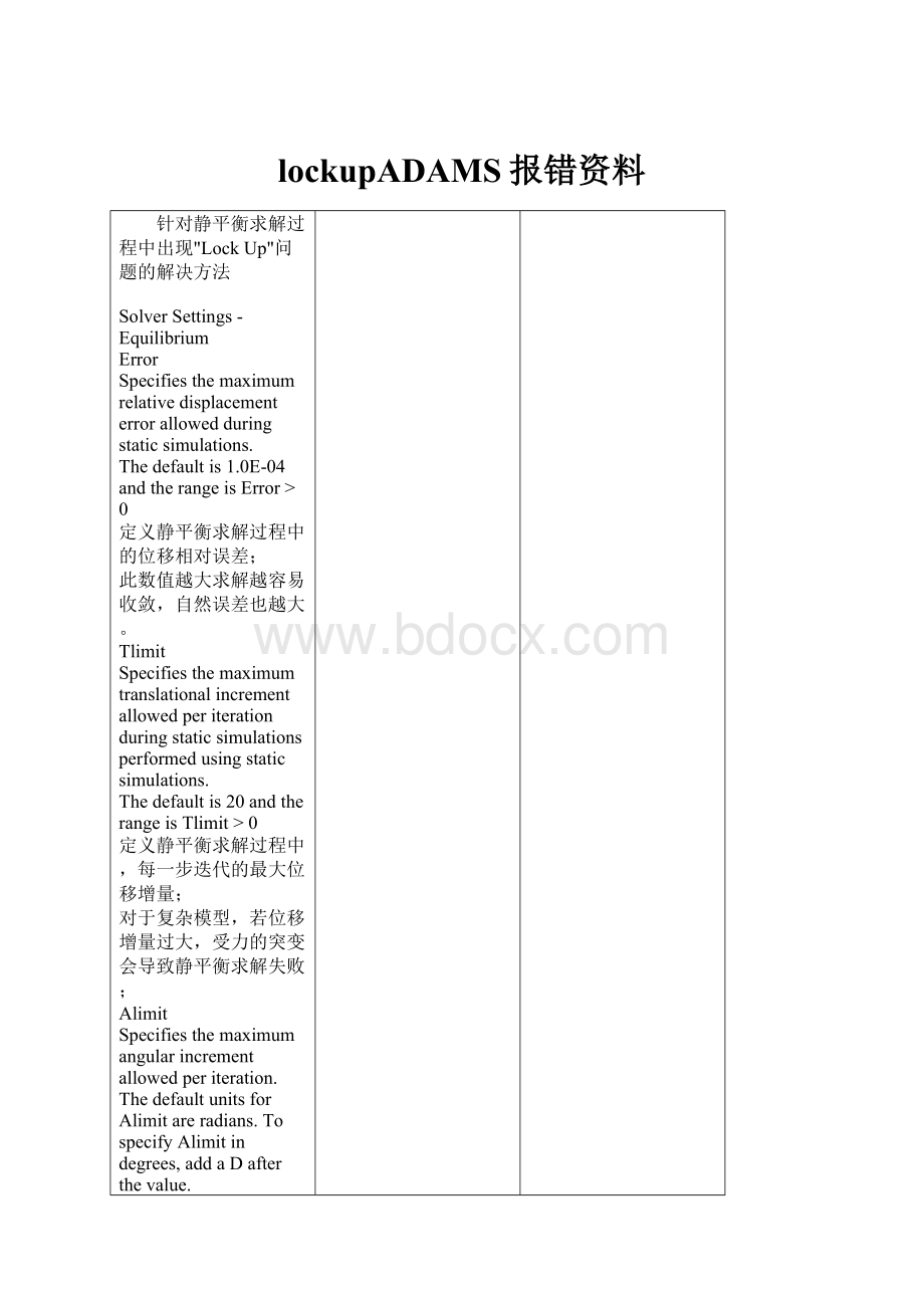
针对静平衡求解过程中出现"LockUp"问题的解决方法
SolverSettings-Equilibrium
Error
Specifiesthemaximumrelativedisplacementerrorallowedduringstaticsimulations.
Thedefaultis1.0E-04andtherangeisError>0
定义静平衡求解过程中的位移相对误差;
此数值越大求解越容易收敛,自然误差也越大。
Tlimit
Specifiesthemaximumtranslationalincrementallowedperiterationduringstaticsimulationsperformedusingstaticsimulations.
Thedefaultis20andtherangeisTlimit>0
定义静平衡求解过程中,每一步迭代的最大位移增量;
对于复杂模型,若位移增量过大,受力的突变会导致静平衡求解失败;
Alimit
Specifiesthemaximumangularincrementallowedperiteration.ThedefaultunitsforAlimitareradians.TospecifyAlimitindegrees,addaDafterthevalue.
Thedefaultis0.17453(10D)andtherangeisAlimit>0
与Tlimit相似,需要注意的地方是默认单位是“弧度”,若需要输入“度”,必须在数值后面加“D”。
如需要设置为10度,输入为10D
Maxit
Specifiesthemaximumnumberofiterationsallowedforfindingstaticequilibriums.
Thedefaultis25andtherangeisMaxit>0.
最大迭代步数,应该与Tlimit和Alimit配合设置;
假设初始状态与平衡状态的位移相差100mm,而Tlimit设置为1,则Maxit需要设置比100大,设置为200应该差不多了。
Stability
SpecifiesthefractionofthemassanddampingmatricesADAMS/Solveraddstothestiffnessmatrix.Addingafractionofthemassanddampingmatricestothestiffnessmatrixcan stabilizetheiterationprocessandpreventtheiterationfromdiverging.Oftenthestiffnessmatrixissingularforasystembecausethesystemisneutrallystable(forexample,thesystemmovesincertaindirectionswithoutaffectingthepotentialenergy).Addingafractionofthemassanddampingmatricestothestiffnessmatrixremovesthissingularityandmakesitpossibletosolveforequilibriumpositions.ThevalueofStability doesnotaffecttheaccuracy ofthesolution,butitdoes affecttherateofconvergence oftheiterationprocess.
Thedefaultis1.0E-05andtherangeisStability0.
施加于刚度矩阵的一个“稳定系数”,使迭代过程更加平稳,更容易收敛;
此数值不影响求解精度,理论上越大使迭代越容易收敛,但越大会使求解越慢。
Imbalance
Specifiesthemaximumforceimbalanceallowedduringstaticsimulationsperformedusingstaticanalyses.
Thedefaultis1.0E-04andtherangeisImbalance>0.
个人理解为与ERROR是相类似的,此处为力的误差;
此数值越大求解越容易收敛,自然误差也越大。
以上各数值,ERROR、Imbalance对求解精度是有影响的,不宜设置过大;.
Error、Imbalance设置越小,Tlimit、Alimit需要设置得越小,Maxit需要设置得越大,求解时间越长;
Tlimit、Alimit与Maxit要配合使用;
Stability根据实际情况设置;
Maxit影响求解失败前的求解次数,Stability影响求解速度。
正确的设置,可以在效率与精度之间得到一个平衡点!
以下是对求解过程的非专业理解:
下图是对于带有前、后板簧的三轴卡车设置参考:
以上纯属个人非专业理解,如有错漏之处,请指出,谢谢,,,
T
iltTable(侧翻试验台)
TestRigTemplate的建立比较简单:
建立一generalpart(table),与ground之间是revolutionjoint,并施加一jointmotion于其上,,,
建立两个mountpart(outputcommunicator是轮胎template中的左侧轮胎),minorrole分别为front,rear等等,,,
mountpart的x,y方向位置由inputcommunicator(粗略的可以输入wheelcenterlocation)确定,z方向与table水平,,,
mountpart与table之间通过bushing连接,bushing的方向为0,90,90,
z方向刚度根据需要设定,一般设定得比较大,主要是限制整车的侧向滑动,
其他方向以及旋转刚度可设为0,或根据需要设置较小的值,,,
将此template输出cmd文件,写字板打开cmd文件,修改其中modelclass为testrig,以及modelclass附近相关代码,,,
SimulationSubmit macro代码编写:
参照4postrig中的macro,此处macro代码实现两个功能:
建立table与tire的关联,
jointmotion的输入,,,
将DemoVehicle改成4WD,只需要对Powertraintemplate进行简单修改即可,主要是增加两输出,,,
Powertrain修改的具体步骤如下:
1.建立inputcommunicator(location,minorrolefront)
2.新建一constructionframe(定义方向0,90,0)
3.建立一generalpart
4.建立cylindricalgeometry
5.建立revolutejoint
6.建立outputcommunicator(mount,minorrolefront)
7.对jointforcediff_outputFunction进行修改
8.新建jointforce(注意Function的定义)
9.另存为R_4WD_powertrain
10.用修改后的template新建一subsystem(minorrolerear)
11.进行shift操作,移动至合适位置
完成效果图
呵呵,两个输出的初始位置反了,geometry还比较娇小,,,
下面对整车assembly进行少量更改:
1.新建TR_4WD_Demoassembly(Powertrainsubsystem使用刚新建的)
2.view---subsystem切换至TR_Front_Subspension
3.将其driveline置为active
4.iso_lane_change工况仿真
5.搞定,,,(附上输出力矩的结果)
以上操作只是一思路,并只是针对DemoVehicle的一种比较简便的方法,,,
并不完全贴合实际的,,,
此处将驱动力分配为前、后各50%,,,
而且前轮的驱动使用了后轮的differentialtorque,,,
具体设置、建法还是得根据实际出发,,,


- 配套讲稿:
如PPT文件的首页显示word图标,表示该PPT已包含配套word讲稿。双击word图标可打开word文档。
- 特殊限制:
部分文档作品中含有的国旗、国徽等图片,仅作为作品整体效果示例展示,禁止商用。设计者仅对作品中独创性部分享有著作权。
- 关 键 词:
- lockupADAMS 资料
 冰豆网所有资源均是用户自行上传分享,仅供网友学习交流,未经上传用户书面授权,请勿作他用。
 《崔万志演讲观后感》.docx
-
《赤壁赋》理解性默写.docx
-
《匆匆》读书笔记15篇.docx
-
《公共政策概论》简答题题库.docx
-
《建设行政执法制度》.docx
-
《平凡的世界》读后感10篇.docx
-
《AUTO CAD》课程标准 2.docx
-
《搭石》课堂教学实录与评析2篇.docx
-
《广东省GSP认证现场检查项目》粤食药监.docx
-
《触摸春天》教案集合9篇.docx
-
《教育评价学》练习题库及答案.docx
-
《公差配合与测量》教案.docx
-
《软件工程》单项选择题答案.docx
-
《网页设计与制作Dreamweaver》试题附答案.docx
-
《易经》与中医学的关系.docx
-
①临床科室医疗质量管理记录册模板.docx
-
###经济开发区企业知识产权情况调研报告.docx
-
《别踩白块度典范版》设计计划文档.docx
-
《村居》教案模板合集七篇.docx
-
《高老头》读后感15篇.docx
-
《故乡》课堂教学实录.docx
-
《鉴定要素细目表》知识.docx
-
《脊椎病因治疗学》word版.docx
-
《马克思主义基本原理概论》考试真题及答案.docx
-
《人性论》读后感人性论读后感3000字.docx
-
《淘气包马小跳》读后感10篇.docx
-
《网页设计与制作》课程标准.docx
-
《小学音乐识谱教学有效性策略的研究》课题研究的中期报告.docx
-
《助产学》考试试题及答案01.docx
-
3分钟熟记精深中医针灸顺口溜附穴位图.docx
-
11大税种税法记忆口诀和计算方法.docx
-
《百家讲坛》观后感20篇.docx
-
精选领导干部任期内履行经济责任制述职报告范文资料.docx
-
贵阳山水黔城人工挖孔桩溶洞穿越方案.docx
-
技术入股合作协议书范本3篇.docx
-
景观照明三遥控制设备建设工程设计合同.docx
-
护理人员日常工作用语和职业规范.docx
-
精编北师大版三年级语文上册知识点汇集精品系列.docx
-
九年级化学上册知识点总结大全.docx
-
建筑业施工企业管理制度.docx
-
精品计算机网络安全技术第二版习题答案.docx
-
沪教版小学语文第一册教案.docx
-
家长开放日工作计划.docx
-
九年级政治上册全册导学案及答案1.docx
-
国家二级建造师《矿业工程管理与实务》测试题B卷 附解析.docx
-
国家注册二级建造师《矿业工程管理与实务》模拟试题 附答案.docx
-
环境整治工作计划.docx
-
会计从业资格考试会计基础第五章练习题.docx
-
海洋文化一条街修缮改造可行性研究报告.docx
-
焊缝形式及坡口尺寸在图纸上是怎样表示地.docx
-
机械设计作业集详解.docx
