 V最新解法Word格式.docx
- 文档编号:18980759
- 上传时间:2023-01-02
- 格式:DOCX
- 页数:24
- 大小:27.12KB
V最新解法Word格式.docx
《V最新解法Word格式.docx》由会员分享,可在线阅读,更多相关《V最新解法Word格式.docx(24页珍藏版)》请在冰豆网上搜索。
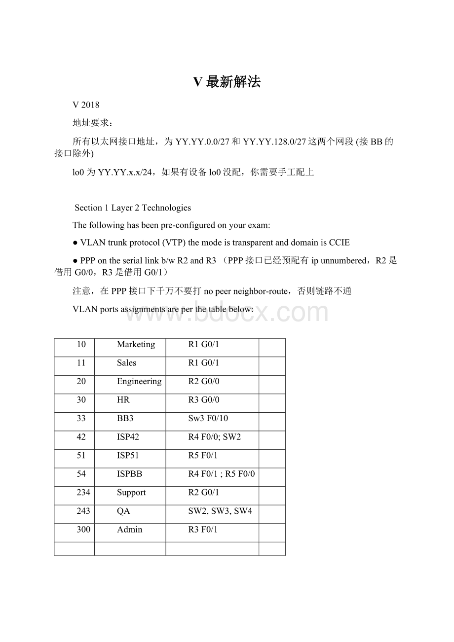
HR
R3G0/0
33
BB3
Sw3F0/10
42
ISP42
R4F0/0;
SW2
51
ISP51
R5F0/1
54
ISPBB
R4F0/1;
R5F0/0
234
Support
R2G0/1
243
QA
SW2,SW3,SW4
300
Admin
R3F0/1
1.1Troubleshootinglayer2switching
Twofaultshasbeeninjectedintothepre-configurations.Theseissuesmayxxxxforcertainportionsofthelab.Youmust……
Scoreonefault:
score2points
Scoretwofaults:
score4points
1、sw3上有一个monitersession1目的接口指向f0/10,要去掉
Nomonitorsession1
2、R1上单臂路由的预配置有错
Intg0/1.11
Encapsulationdot1q11native--------------这个native要去掉,多余的
1.2Provisioningarobustlayer2core
Configuretheappropriatefeatures,accordingtothefollowingrequirements:
⏹Deploying802.1wonallfourswitches
所有交换机启用RSTP
spanning-treemoderapid-pvst
⏹Ensurethatthespanningtreeenterstheforwardingstateimmediatelyforalltheaccessswitchportsbypassingthelisteningandlearningstates.Donotchangethedefaulttheconfigurationaffectingallaccessswitchports(Portsconnectedtothebackbonearenotconsideredaccessports).
启用portfast,应该只在access接口下启用,而且接backbone的接口不用敲
Intxxx
spanning-treeportfast
以下几个接口要启用:
SW1和SW2:
F0/2、F0/3、F0/4、F0/5
⏹AvoidtransmittingBPDUsonanyaccessswitchport.IfaBPDUisreceivedonanyoftheseports,theportshouldbeshutdownimmediately.Useasinglecommandperswitchtoaccomplishthis.
这个是要求启用bpduguard
SW1-SW4:
spanning-treeportfastbpduguarddefault
⏹Ensurethatall4switchesareabletoreacttoaunidirectionallinkfailureforanyswitchtoswitchport.Theaffectedportshouldbedisabledintheeventofalinkfailure.
Interrangef0/19-24
udldportaggressive
1.3SwitchTrunkPorts
Configurethetrunkportsb/wsw1,sw2,sw3andsw4accordingtothefollowingrequirements:
⏹Use802.1qencapsulationsonallports
⏹Theswitchesshouldnotactivelyattempttoconvertthelinktoatrunklinkbynegotiatingthetrunkmode.
手动配置trunk,不要协商,关闭DTP
SW1–SW4:
interfacerangeF0/19-24
switchporttrunkencapsulationdot1q
switchportmodetrunk
switchportnonegotiate
⏹UtilizeetherchannelbetweenalltheswitchesinterconnectionsusingtheIEEEstandardprotocoltoactively.
使用LACP主动模式协商etherchannel
IntXXX
channel-group12modeactive
⏹EtherchannelloadbalancingshouldbeaccomplishedbydestinationIPaddress.
SW1-SW4:
port-channelload-balancedst-ip
⏹Configureportoffa0/1onsw2.ensurethatonlyVLANSalesandMarketingareallowedonthatport.
R1上做了单臂路由,SW2上要做trunk
SW2:
interfaceFastEthernet0/1
switchporttrunkencapsulationdot1q
switchporttrunkallowedvlan10,11
switchportmodetrunk
switchportnonegotiate
R1:
interfaceFastEthernet0/1.10
encapsulationdot1Q10
ipaddress1.1.0.65255.255.255.224
interfaceFastEthernet0/1.11
encapsulationdot1Q11
ipaddress1.1.0.97255.255.255.224
R1上的配置其实已经预配好了的,但是可能有以下错误,要改过来
Endot1q11native--------------这个native要去掉,多余的
1.4SpanningTreeRootSwitch
Configuretheswitchesaccordingtothefollowingrequirements:
⏹Sw1shouldbetherootswitchforallVLANs.Ensuretogivesw1highestprobabilityevenifanotherswitchisinsertedintopologyinthefuture.
⏹Sw4shouldneverbecometherootforanyVLAN.Ensurethisoccurwithoutusingthe“spanningtreepriority”command.
SW1上将优先级设为0。
SW1:
Spanning-treevlan1-4094priority0
SW1-SW3与SW4连接的etherchannel接口做根保护
SW1-SW3:
Intpo14、24、34
Spanning-treeguardroot
1.5SwitchManagement
⏹ConfigureSW1sothatadynamicentryinthemacaddresstablefortheEngineeringVlanwillbeagedouttwiceasfastasfortheothersVLANs
(在VLAN20的mac-addresstable中,动态条目的ageout-time是其他VLAN的1/2.)
SW1:
mac-address-tableaging-time150vlan20
1.6PortMonitoring
Configureportmonitoringonsw3accordingtothefollowingrequirements:
⏹Thetransmitandreceivetrafficonportsfa0/1throughf0/8andtheetherchannelport-channel(fa0/19andfa0/20)shouldbemonitored.
⏹AcopyofthetrafficshouldbeforwardedtoFa0/11
SW3:
monitorsession1sourceinterfacef0/1-8,po31both
monitorsession1destinationinterfacef0/11
1.7ImplementFramerelay
ConfigureR1andR3forframerelay,configuringR5astheframerelayswitchaccordingtothefollowingrequirements:
●UseLMIautosenseonR1andR3andciscoLMIontheframerelayswitchR5
●Donotuseanystaticframerelaymaps
●Useciscoframerelayencapsulation
●UsetheDLCIsassignmentsfromthetablebelow:
●Usethepoint-to-pointinterfacetype,usetheDLCInumberassub-interfacenumber
●Keepthelayer3addressingandroutingrequirementsinmindwhenconfiguringframerelay(useonlytheipaddressesspecifiedinDiagram1.)
FramerelayDLCIAssignments:
R10/0/0
FRSwitch0/0/0
221
R30/0/0
FRSwitch0/0/1
223
R5:
Frame-relayswitching
Ints0/0/0
Encapsolationframe-relay
Frame-relaylmi-typecisco
Frame-relayintf-typedce
Frame-relayroute221ints0/0/1223
Ints0/0/1
Frame-relayroute223ints0/0/1221
R1与R3之间还要做PPPOVERFRAM:
R1、R3:
interfaceSerial0/0/0
encapsulationframe-relay
noframe-relayinverse-arp
interfaceserial0/0/0.221point-to-point//用DLCI号做子接口号
frame-relayinterface-dlci221pppVirtual-Template1
interfaceVirtual-Template1
ipunnumberedlo0//要借用lo0地址,这里在后面还要绑定PPP的多链路,还要去掉
注意:
在1800上用点到点子接口做pppoverframe-relay时,要先把物理接口down掉,配好子接口之后,再up,否则会弹出以下提示:
%PVCalreadyassignedtointerfaceSerial0/0/0
Section2Layer3Technologies
●Afterfinishingeachofthefollowingquestionsmakesurethatallconfiguredinterfacesandsubnetsareconsistentlyvisibleonallpertinentroutersandswitches.
●DonotredistributebetweenIGPprotocolandBGPprotocol
●YouneedtopingBGProuteonlyifstatedonaquestionotherwisetherouteshouldbeonlyontheBGPtable.
●Bytheendofthissectionallsubnetsonyourtopology,includingloopbackinterfacesmustbereachableviapingfromanywhereinthetopology.Thebackboneinterfacesneedtobereachableonlyiftheyarepartofthesolutiontoaquestion.
●TheaddressesconsideredtobeinternaltotheMPLSmustnotbereachablefromoutsidetheMPLSnetwork.
●Theloopbackinterfaceswillbeseenasahostroute/32ontheroutingtableunlessstatedotherwiseinthequestion.
2.1ImplementIPv4OSPFPart1
ConfiguretheOSPFarea0andarea51aspertheIGPtopologydiagramandthefollowingrequirements:
●TheprocessIDcanbeanynumber.
●Loopback0interfacesshouldbeadvertisedinanyOSPFareaforallnon-MPLSDevices.
●UpdatesshouldbeadvertisedonlyoutoftheinterfacesthatareindicatedintheIGPtopologydiagram.
●Sw1shouldalwaysgenerateadefaultrouteintotheOSPFdomain
●TheBB1linkshouldbeseenasExternalOSPFroutesintheOSPFdomain.
●Makesurethattheinterfacesareseeninthecorrectareaasperthediagram.
●DonotcreateadditionalOSPFareas.
Routerospf100
default-informationoriginatealways
Route-mapCONN
Matchinterfacef0/10//BB1接口
Redistributeconnectedsubnetsroute-mapCONN
2.2ImplementIPv4OSPFPart2
ConfiguretheOSPFarea1aspertheIGPtopologydiagramandthefollowingrequirements:
●Sw2shouldalwaysgenerateadefaultrouteintotheOSPFdomain
●TheBB2linkshouldbeseenasExternalOSPFroutesintheOSPFdomain.
2.3ImplementIPv4EIGRP
●ConfigureEnhancedInteriorGatewayRoutingProtocol(EIGRP)10betweenR4andR5aspertheIGPtopologydiagram.
︒Bothrouter'
sloopback0shouldbeseenasanEIGRPexternalroutebytheneighbor.(这就是要求R4和R5的Lo0口要重分布进EIGRP10啦)
●ConfigureEIGRP100aspertheIGPtopologydiagram.
︒EIGRPupdatesshouldbeadvertisedonlyoutoftheinterfacesindicatedintheIGPtopologydiagramonly.
︒ConfigureSW3suchthatitwillnotreceiveanyEIGRPqueries.SW3shouldalsonotsendoutanyinformationaboutitsroutestotheEIGRP100neighbors.Donotconfigureanykindofoutgoingfilteringtoaccomplishthistask.
︒Usearoute-maponSw3totaganyCLASSAnetworkaddressroutesreceivedfromBB3withatagof200.(TheACLmustcoverthewholeClassAaddressrange)
︒OnSW3redistributeEIGRP100intoOSPF.Summarizethefollowingroutesintoanaggregate198.0.0.0/8:
⏹198.1.1.4/30
⏹198.2.1.0/24
⏹198.2.3.0/24
⏹198.2.5.0/24
Routereigrp100
Eigrpstubreceive-only
Access-list10permit0.0.0.0127.255.255.255
Route-mapTAG
Matchipadd10
Settag200
Route-mapTAG20
Distribute-listroute-mapTAGinvlan33
Redistributeeigrp100subnets
summary-address198.0.0.0255.0.0.0
2.4ImplementMPLSPart1(4Pionts)
ConfigureMPLSpertheMPLStopologydiagramaccordingtothefollowingrequirements:
●NametheVRFas“vpnA”(useRD=100:
1androutetargetimportan


- 配套讲稿:
如PPT文件的首页显示word图标,表示该PPT已包含配套word讲稿。双击word图标可打开word文档。
- 特殊限制:
部分文档作品中含有的国旗、国徽等图片,仅作为作品整体效果示例展示,禁止商用。设计者仅对作品中独创性部分享有著作权。
- 关 键 词:
- 最新 解法
 冰豆网所有资源均是用户自行上传分享,仅供网友学习交流,未经上传用户书面授权,请勿作他用。
 对中国城市家庭的教育投资行为的理论和实证研究.docx
-
二年级下册数学练习题大全.docx
-
二十年后回故乡的优秀作文.docx
-
软基换填施工方案.docx
-
《黑白装饰画》教案.docx
-
课堂教学改革实施方案5篇.docx
-
返璞归真简约致美解读《给予树》教学设计语文.docx
-
离职证明范本精选多篇.docx
-
《天局》全文.docx
-
我害怕作文集合15篇.docx
-
伏魔战记39详细攻略.docx
-
幼儿园学期计划.docx
-
雅思分类打印版Word格式文档下载.docx
-
年产1万吨竹子纤维加工项目可行性研究报告文档格式.docx
-
电商产业化项目投资经营商业计划书Word文件下载.docx
-
医学多媒体课件的设计与制作Word文档格式.docx
-
中学生中秋节想象作文Word格式.docx
-
等保20之漏洞扫描系统技术方案建议书Word文档格式.docx
-
培训学校个人工作计划模板5篇Word格式.docx
-
北京各区二模试题分类汇编文言文阅读Word文档下载推荐.docx
-
不同职业病危害因素的防护常识Word格式文档下载.docx
-
一年级上册同音形近字练习汇总Word文档格式.docx
-
班级家长会上班主任教师讲话稿Word下载.docx
-
科斯塔环载波恢复Word文件下载.docx
-
浙教义务版六年级语文下册教案 花潮Word文件下载.docx
-
集成电路设计与集成系统专业Word格式文档下载.docx
-
开工第一课专题讲座观后感文档格式.docx
-
东城区学年第一学期高三期末化学试题及答案Word格式文档下载.docx
-
苏教版六年级语文下册第七单元测试题Word格式文档下载.docx
-
学长征精神做红色传人活动方案文档格式.docx
-
读书笔记150字30篇文档格式.docx
-
中级经济法考前必背法条精华版备考资料Word格式.docx
-
氧化还原法制备纳米铜研究报告综述Word下载.docx
-
中考物理知识点填空Word下载.docx
-
工程量清单计价实例含图纸2Word格式文档下载.docx
-
挽联横批大全Word下载.docx
-
小学三年级下册综合实践活动教案 全册Word下载.docx
-
物流软件操作题库Word格式文档下载.docx
-
linux程序设计复习题Word文档下载推荐.docx
-
七绝相思一百首文档格式.docx
-
开心英语三年级上册Word文档格式.docx
-
中药记忆表格Word文件下载.docx
-
改革开放与创新发展考试答案Word文档格式.docx
-
高二数学教案正态分布教案Word文档格式.docx
-
汽车冲压件的分类资料Word格式.docx
-
人教版小学二年级数学上册两位数竖式加减法 121Word格式.docx
-
炼油废水处理Word格式文档下载.docx
-
互联网+高校兼职平台项目创业计划书文档格式.docx
-
XX地区综合生态农业示范园建设项目可行性研究报告Word文件下载.docx
-
人教版六年级语文下册三单元质量分析卷及答案二篇Word格式文档下载.docx
-
工程项目部岗位职责Word文件下载.docx
